Lab 1: Go Autonomous
Team size: 4
Prelab Help Sheet: html
Writing Assignment: html
1 Introduction
In this lab you will transform the ROV (remotely operated vehicle) used in E79 into an AUV (autonomous underwater vehicle). An ROV is controlled from the surface through long cables, but an AUV carries an autonomous controller on board. While the AUVs you build in Lab 1 will all look the same, you will have a chance to modify these vehicles during the project. By end of semester, each robot will be configured and equipped for unique ocean-sampling experiments.
After successful completion of this lab, you will be able to…
Lab 1 is completed in teams of 4.
Be sure to read the Lab Overview to learn about safety requirements, expensive equipment handling and other rules. You must review all SAFETY QUESTION boxes below as part of prelab. If you ever reach a safety question box and either can’t answer it or feel unsure, grab an instructor.
At the end of the lab, you need to submit a completed submission sheet (see links above) on Canvas. Specifications for each part of the lab are included on the submission sheet.Recall that no late work is accepted, we will grade whatever is submitted before the deadlines. Since multiple submissions are allowed, you may want to submit a less-than-perfect draft early as insurance against missing the deadline.
2 Motherboard Assembly
A motherboard has been designed to interface the major electrical components of your AUV. You will assemble it in this section. Familiarize yourself with the components on the motherboard by reading the Introduction to the E80 Motherboard, and the Motherboard Assembly Document.
There are two ways that you can damage your motherboard irreparably during this process, and you should take precautions against each of them.
- Soldering components in the wrong position or orientation (e.g., screw terminals facing inward or header on the back side of the board), which is very difficult to rework. Double check that you are using the correct header and try fitting all the pieces together before soldering.
- Flipping power and ground by attaching your battery or power supply leads backwards or soldering the red and black wires to the incorrect terminals on the motherboard. Have an instructor or proctor check your battery connector, and make sure to heed the warnings in the assembly guide.
- Find the parts you need for your motherboard in the parts rack on the supply table. There is set of parts racks in both B171 and B181.
- Label your board: Before you begin assembly, write your section number, team number and board version on your board. This will be version 1 for all of you, you will increment your version if, for example, your board blows up and you have to make a new one.
- Take precautions to keep everything working before soldering
- Double check that you are using the correct header and try fitting all the pieces together before soldering.
- Have an instructor or proctor check your battery connector and power supply connector polarity.
- Follow the instructions in the Motherboard Assembly Document to build your Motherboard.
- Cover the back of your motherboard with insulating foam sheet using these instructions to prevent inadvertent short circuits when you set it down.
- Find a sharpie and color the GND side of your P.S. screw black, so that you don’t forget the polarity of the connector.
3 Motherboard Validation, IMU Calibration, and IMU Error Measurement
Your motherboard has a circuit on it called an inertial measurement unit (IMU), specifically an LSM303AGRTR , which allows you to measure acceleration and magnetic fields. This is a useful sensor that we will explore more later in the course. We are just getting started with the sensor in this section by calibrating the output and measuring its noise statistics. This sensor is also useful because you can only measure its output if your motherboard is working correctly. The tests in this section will ensure that your Teensy can listen to the IMU, write to the SD card, and drive the motors.
First, test your motherboard:
- Sign out an SD card from an instructor.
- Put your Teensy and your SD card into your motherboard and program the Teensy with
E80_Lab_01.inofrom the E80 codebase from Github. This sketch will turn on one motor for four seconds if it is working properly, so be sure your motors are clear of any obstructions (especially your hands!) when you run the code. - Provide power to the Teensy using either your battery or the power supply terminals (be careful with the polarity!). You can use the power supply terminals if your battery is still charging. Several lights should turn on, including PWR LED, the IMU LED, the SD LED, and a small blinking LED on top of the Teensy.
- You have the option of plugging in your USB cable so you can use the serial monitor to watch the Teensy’s serial output as it runs.
- Remove power from your board (you do not need to remove the USB cable if it’s plugged in).
- Take out the SD card and put it into your computer.
- Take the INF and BIN files off of the SD card and read them according to the following instructions.
- The Teensy creates two files to save data every time it runs: an INF file which contains text and a BIN file which contains your measured data in a binary format.
- Special programs are required to decode the binary data, and those programs also depend on having a matching INF file. We provide a MATLAB script for reading SD card data: logreader.m.
- These links provide sample INF and sample BIN files so you can test the MATLAB scripts during prelab. The sample file is very noisy, so it can’t be used to find answers to the questions later in this Section.
- Verify that you are saving the following data to your SD card: acceleration values from your accelerometer, magnetic field strengths from your magnetometer, roll, pitch and yaw angles calculated from your IMU measurements, and motor PWM values.
- Verify that your motherboard can drive motors by attaching motors to motor ports A, B and C, then modifying and running
E80_Lab_01.ino(which you set up in lab 0) to drive each of them. If your motors are not ready, you can measure the voltages at screw terminals A, B and C to observe whether they are being correctly applied by your software.
Please be very careful when connecting or disconnecting the micro USB cable to the Teensy!! Pull or push laterally while holding down the connector with your other hand. They are fragile and can be pulled off the board easily.
You can put your Teensy into programmer mode manually by pressing the button on top of the Teensy. This button won’t restart a program currently running on the Teensy. Instead, it deletes all the code on the Teensy so it can be reprogrammed. If you just want to rerun your current program, remove power from the Teensy (maybe using the black power rocker switch) and then restore power.
Second, analyze the data from your accelerometer:
- Lay your board flat on its standoffs, then take ten seconds of accelerometer data. Determine the mean, the standard deviation, the standard error, and the 95% confidence bounds for a static acceleration measurement in the z direction.
- Figure out the value the accelerometer reports when it is experiencing zero acceleration on each axis. You may need to run your program a few times while holding the board in different orientations to make each axis zero.
- Use the acceleration due to gravity to figure out the size of one ‘accelerometer unit’ in your saved data: i.e.: if your accelerometer reports a value of 1, how many m/s^2 of acceleration is the accelerometer experiencing? Note that accelerometers usually report an unusual unit called “milli-g”, thousandths of acceleration due to gravity, so you should expect one accelerometer unit to be some number of milli-g, which in turn you can represent as m/s^2. (Milli-g is abbreviated mg, confusingly.)
- Use the Student’s T Test to determine if the zero values on each of your axes are statistically different from one another.
4 Penetrator and Motor Assembly
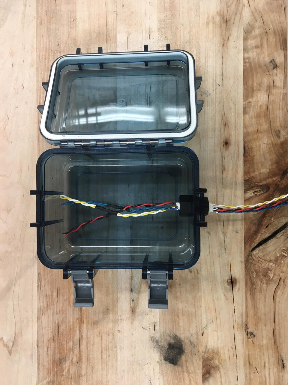
In E80 we use special bolts to make waterproof electrical connections across a robot (Figure 1 (a)), and we refer to them as penetrators. Penetrators are combined with a nut and gasket (Figure 1 (b)) to make waterproof seals on project boxes (Figure 1 (c)). This figure shows two important details about using penetrator bolts: the threads must point INTO the box and the washer must be OUTSIDE the box.
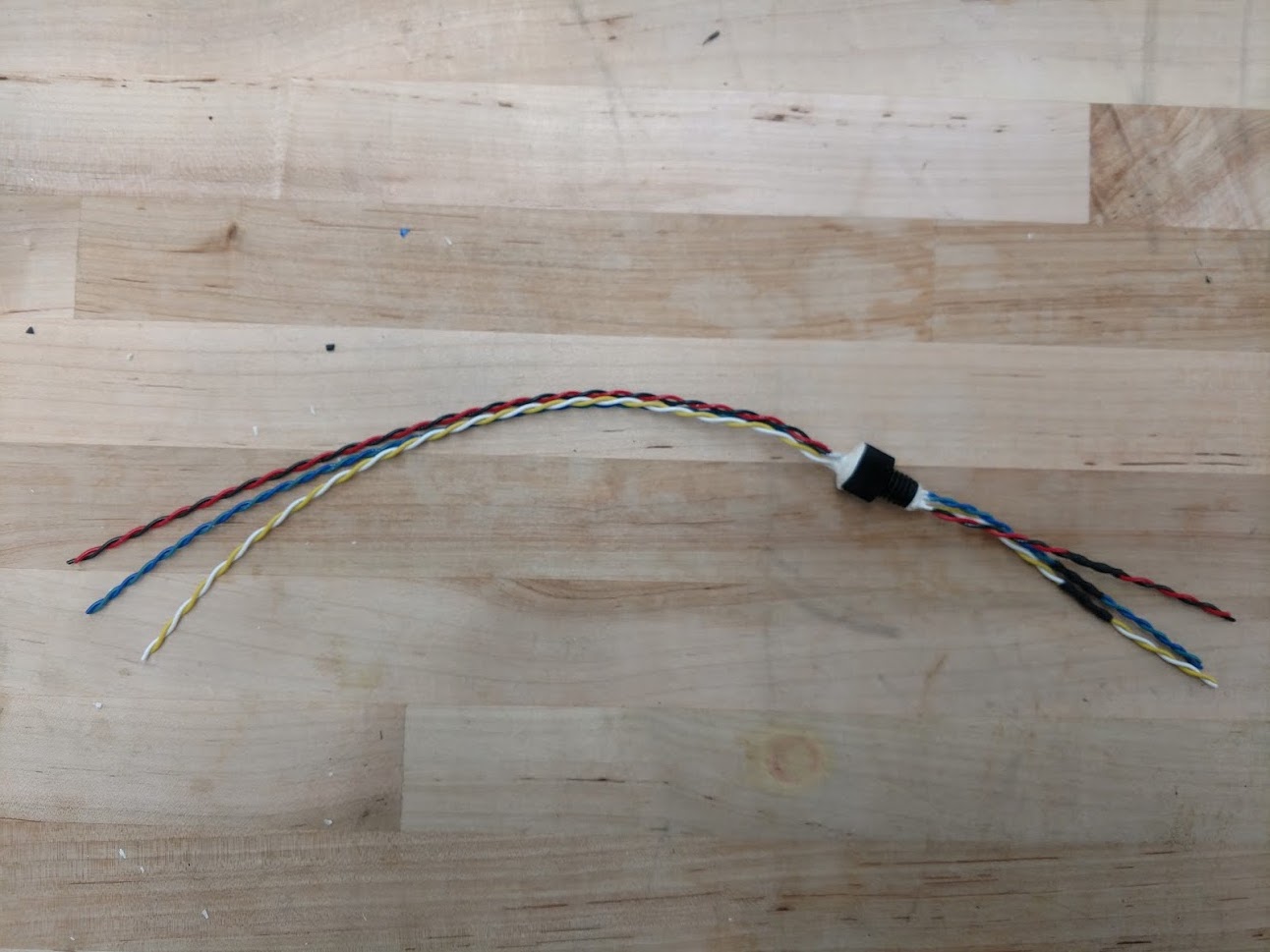
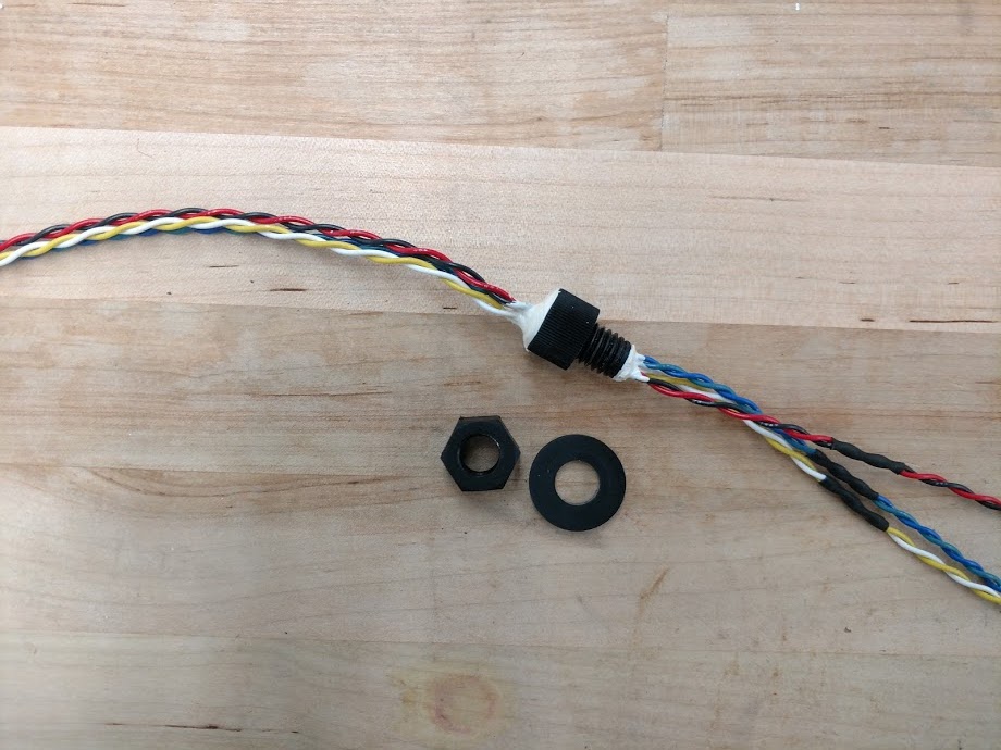
These penetrators have six wires passing through them because your AUV will use three motors, which you must prepare.
- You will need a total of 3 motors. If necessary, you can prep new motors as you did in E79, but your time will be very limited if you must build motors. Instructions can be found here.
- If you have not done so during Lab 0, test your motors using a power supply to make sure they work by supplying 6VDC:
- If the current draw during this test is more than 500 mA, then the friction in your motor is likely to severely limit your top speed; consider debugging it.
- Selecting motors that have similar current draws may simplify your software because the motors will exert similar thrusts at the same level of applied PWM.
- Make sure your motors still work when they are submerged in water.
- If the current draw during this test is more than 500 mA, then the friction in your motor is likely to severely limit your top speed; consider debugging it.
- Solder the leads of your three motors. Your motors will be OUTSIDE of the box, so your solder joints will need to be waterproofed with heat shrink tuing. After putting heat shrink on your wires, solder the motor leads to the twisted pair on the non-threaded side of your penetrator bolt. Finish Waterproofing your solder joints with heat shrink tubing.
- Test that all three motors work when the waterproofed solder joints are underwater.
5 AUV Assembly
First, assemble your project box:
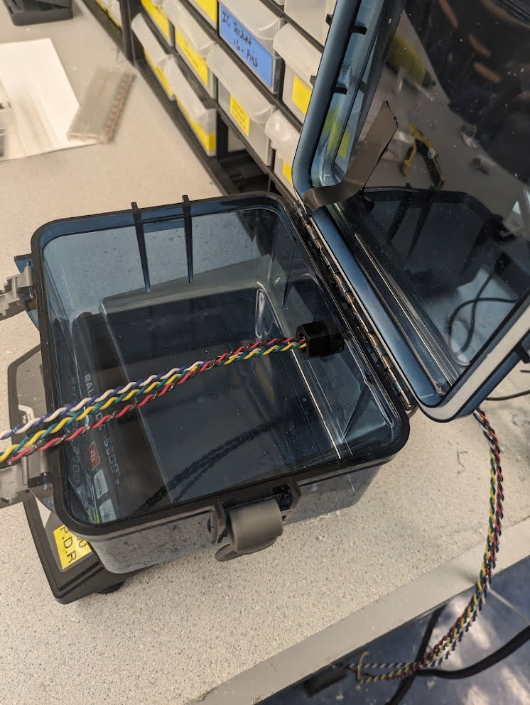
- Find your waterproof box and remove the protective paper tape on the rubber seal.
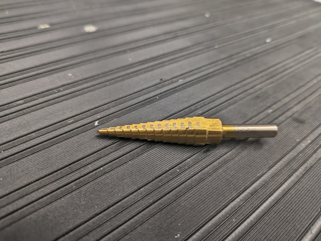
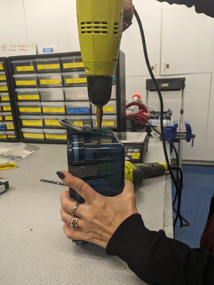
- Drill out your penetrator holes using a step drill bit. DO NOT USE A NORMAL DRILL BIT. Pictures of a step drill bit and the drilling process are in Figure 2 (a) and Figure 2 (b) . The inner diameter of your hole should be 0.5 inches.
- Attach your penetrator and motor assembly to the box (remember threads are in and washer is on the outside). This is pictured in Figure 2 (c)
- Hold your box and penetrator combination underwater to check for leaks. DON’T perform this test with any electronics or batteries in the box.
- If you find leaks, fix them before proceeding. Ask for help if you’re stuck.
Second, assemble your robot:
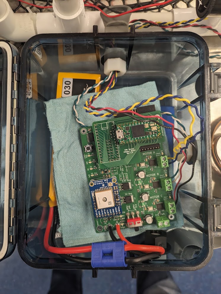
- Dry your box and place your battery, motherboard and Teensy into the box. See Figure 3 (a).
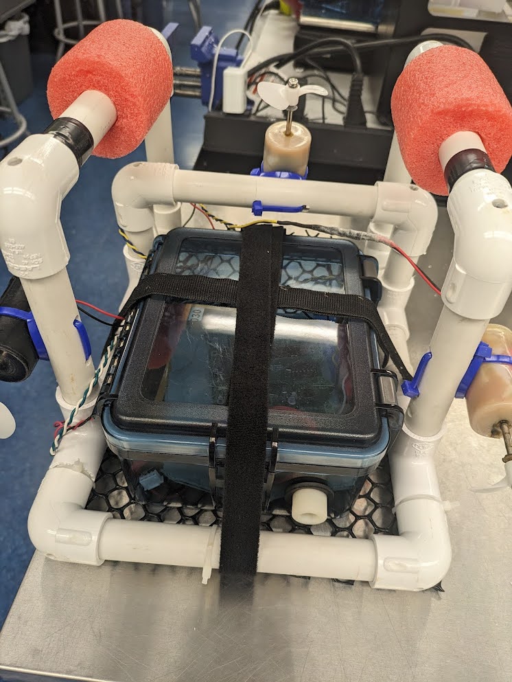
- Use Velcro to attach the box to a PVC robot frame. Make sure to attach a plastic cargo mesh on the bottom of your frame for carrying payloads. See Figure 3 (b).
- Use zip ties to secure the cargo mesh to the robot frame.
Third, ballast your robot so that it is close to neutrally buoyant.
- Determine how much mass to add. To do this, it helps to know the mass of your robot, and that the robot (including motors and two 1.25’’ foam blocks, but not including the watertight box) has a buoyancy force measured to be approximately 10 N. You can do this approximately in prelab with a guess at your robot’s mass.
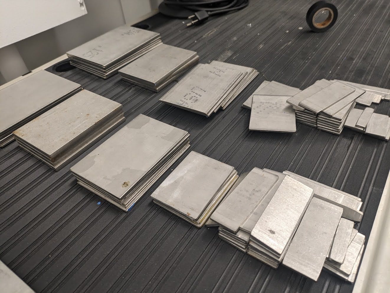
- Select weights for ballasting. Pictures of some of the weights we have available are in Figure 4 (a). Be mindful that their distribution inside of your payload box could affect the resting pitch, yaw or roll of the robot. It may be useful to adjust the resting buoyancy, pitch, yaw, and roll of your robot with the waterproof box before attempting the obstacle course in section 7.
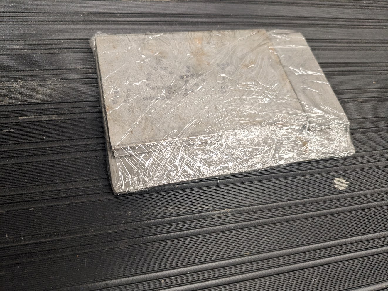
- Protect against metal shorts. Many of the weights we use are metal, so they can short the back of your motherboard. Make sure the back of your motherboard is covered with insulating foam or electrical tape before setting it on top of your ballast. We also recommend wrapping your ballast in plastic wrap as shown in Figure 4 (b).
6 Open Loop Control Navigation
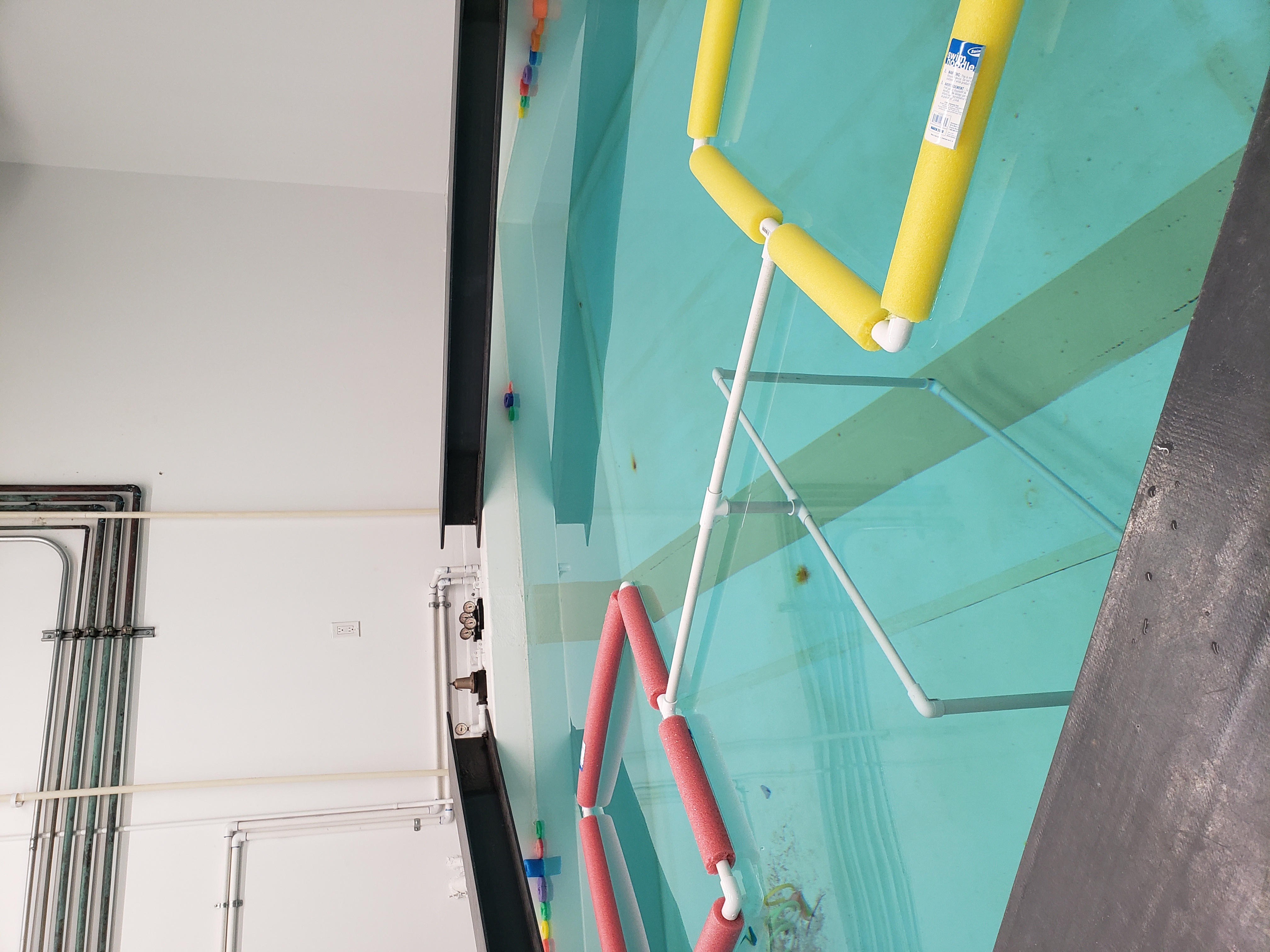
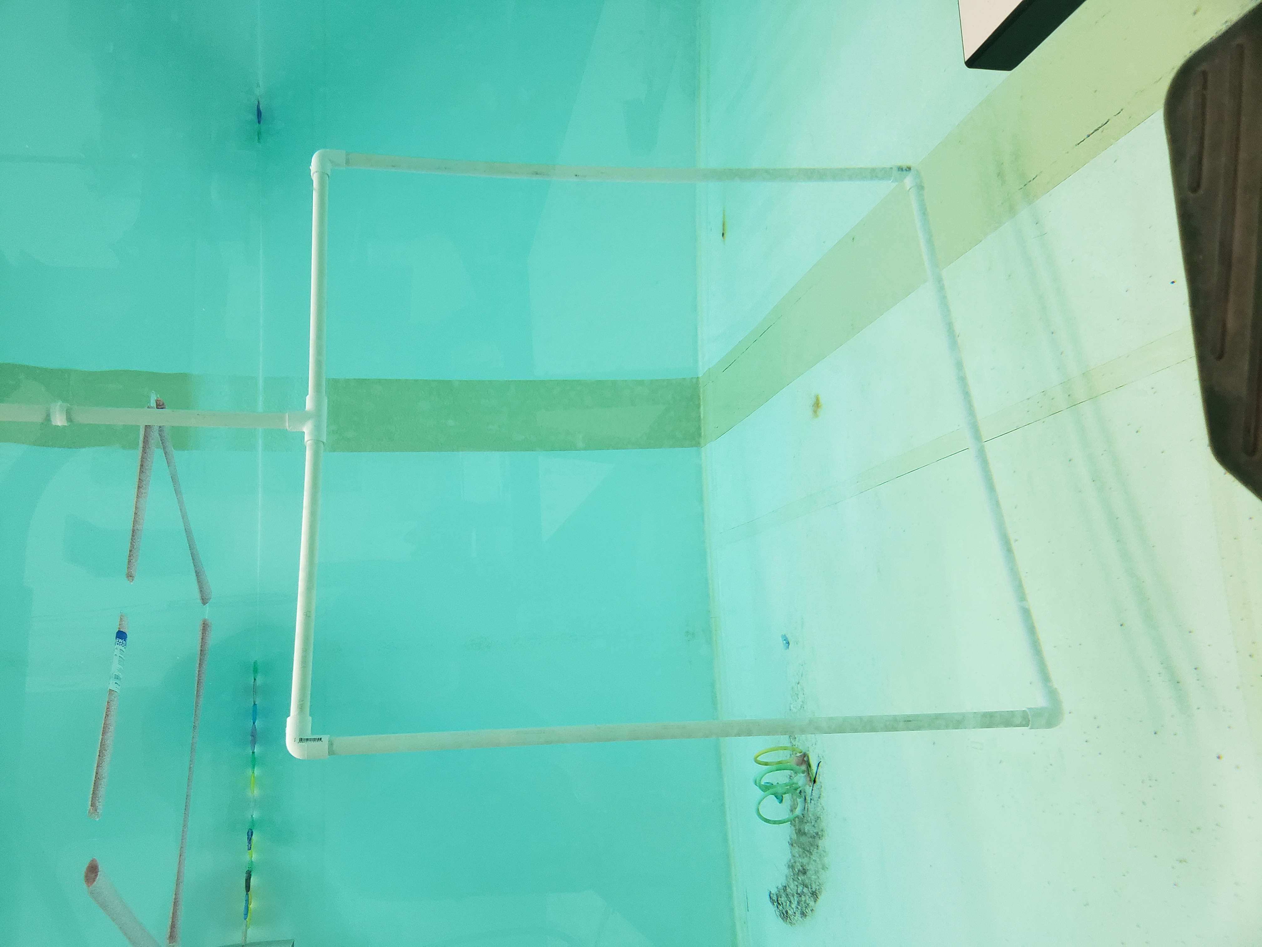
A simple obstacle course will be set up in the test tank. The obstacle course is pictures in Figure 5 and Figure 6. You must navigate your robot through the 3 hoops, starting at the surface in one hoop, diving through the second and surfacing in the third.
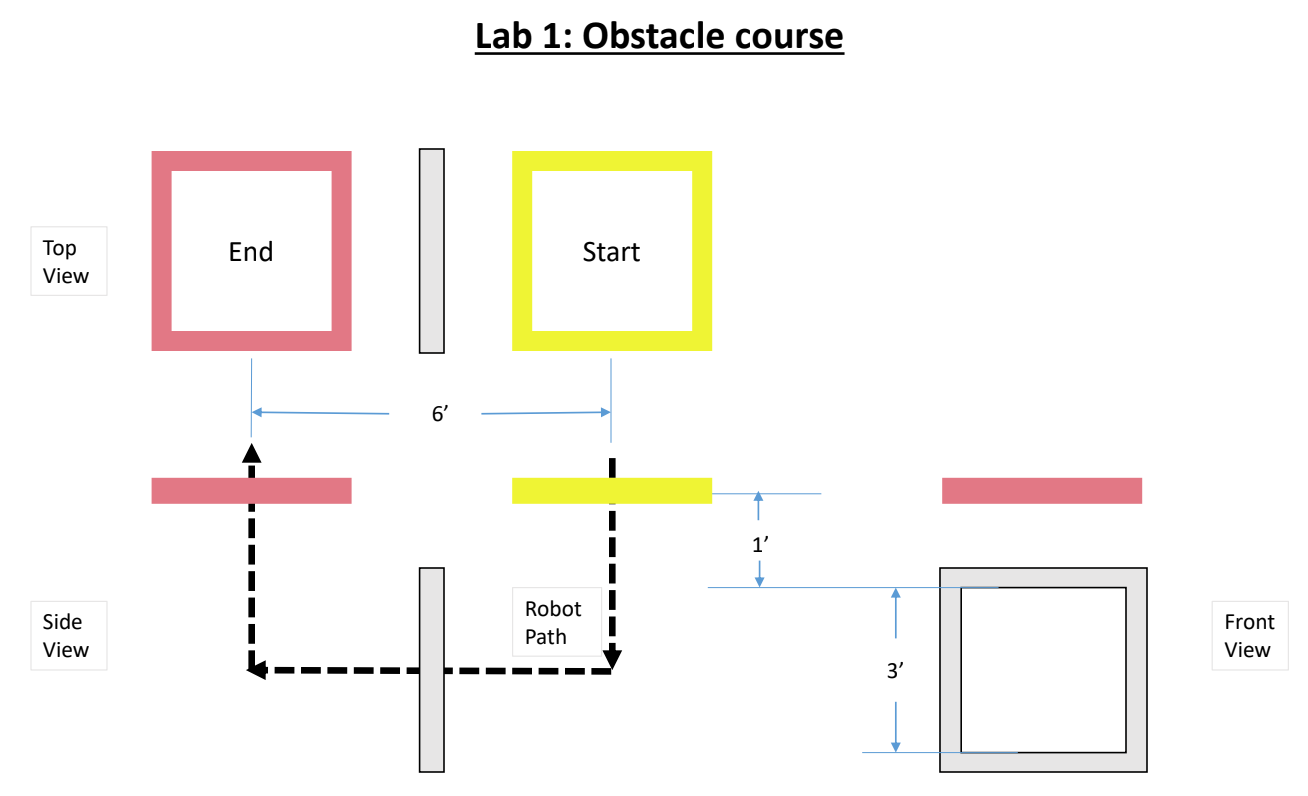
- Modify
E80_Lab_01.inoto direct your robot to traverse the course so that it ends within the red hoop (3). You can assume your AUV can start in the middle of the yellow hoop (1). Make sure your code accounts for the time you will need to seal up the waterproof box, attach it to the robot frame, and position it in the water. - Be sure to test your code with your robot ahead of time, in air and in a dunk tank, before you visit the test tank room. It is important to know how to control each motor, including which direction each motor turns. It is also important to verify that you are correctly logging data.
- Get your robot checked by an instructor, go to the tank room, and deploy your robot. You will only have 5 attempts in the test tank room.
Part of the goal of this lab is to convince you that open loop control does not work very well. Robots navigating open loop can go off course because of motor behaviors, currents in the tank, misplacement in the launch area, or many other reasons. Closed loop control can address some of these issues. Don’t worry if your robot doesn’t complete the obstacle course.
7 Acceleration and Orientation Data
Plot the AUV acceleration data from the experiment in Section 6 as a function of sample number. Confirm that positive acceleration is in the correct direction. Confirm qualitatively whether the measured acceleration data matches your expectations, and retake data if needed.
Finally, consider the E79 robot model in Equation 1 and the E79 motor thrust curve in Figure 7. Use the model and the thrust curve to make predictions of your peak acceleration when your motors first turn on from rest. Compare that prediction to your measured data.
\[ m\ddot{x} = F_{thrust} - b\dot{x} \tag{1}\]
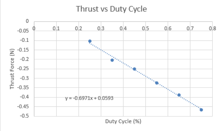
This comparison is a good example of how E79 can be applied and a good example of how to compare experimental data to theory. The comparison also can be affected by differences between your motors compared and this motor curve, and that variability makes another case for using closed loop control.
IMPORTANT CLEANUP: Please return the battery charger to the center table. These will be shared among the different lab sections. Also, put your ballast weights, board, Teensy, penetrator bolt (with motors), battery and robot frame in your labelled Tupperware container in the cupboard. Please return SD card and SD card reader to a proctor or instructor.