Lab 2: Basic Electrical Measurements
Team size: 2
Prelab Help Sheet: html
Writing Assignment: html
1 Introduction
In this lab you review the use of electrical test equipment, calculate the uncertainty in a measurement based on its components, and apply equivalent circuit models to understand instrument loading and op-amp buffers. Electrical instruments and op-amps are used in every lab in this course, so we are doing this lab to build your toolkit for making experimental measurements. Another goal of the lab is for you to practice error analysis and propagation.
After successful completion of this lab, you will be able to…
This lab will be completed in sub-teams of two students. Before the lab you must decide how you will split your team. Two other labs (labs 3 and 4) will also be completed as sub-teams, and you must use a different sub-team for each of these labs. Each sub-team will be responsible for its own submission sheet. Pre-lab work may still be carried out with your whole team, but be sure each sub-team is ready to tackle the in-lab work independently. Even though your team will be split into two sub-teams, you will only have access to one motherboard/Teensy assembly. Plan your work carefully so that you share it equitably. You will let us know about your sub-team choices using a Canvas feature called “self-selected teams,” so give yourself a little extra time to turn in your submission sheet and sort that feature out.
2 Logging Analog Data with the Teensy
The Teensy contains an analog to digital converter which can measure analog signals on many of its pins. In this section you will take your first analog measurement with the Teensy. You will use two different pieces of software to log data from the Teensy in this section: A program on your Teensy (written in Arduino code) will sample data, and a MATLAB program will interpret serial data sent by your Teensy. These programs sample the voltage on input A0, which is identified on the silk screen on the back of your motherboard.
Always connect to your Teensy pins through the E80 motherboard, which has protection circuits designed to prevent damage to the Teensy.
Set up the analog meaurement,
- Attach a wire to the empty A0 hole on your motherboard. Wire-wrapping solid core wire works well, a male-male jumper wire works OK. DO NOT SOLDER IT. We will solder a header there later, and desoldering a wire will make that more difficult.
- Find a way to make a connection between your motherboard ground to your signal generator ground.
Measure a first set of data
- Connect a 200 Hz, 1 Vpp, +0.4 V offset sinusoidal wave from a signal generator to the analog pin A0 and run the following sketch on your Teensy:
matlab_logging.ino. - While
matlab_logging.inois running and the Teensy is connected by USB, usematlablogging.mto receive a vector of data from the Teensy.
- You may need to modify the
matlablogging.mso that it points at the COM port which is correct for your Teensy. matlablogging.mcan’t access your COM port if the Arduino serial monitor is open, so be sure that it is closed.- Sometimes COM ports get stuck in unusual states and MATLAB can’t access them. Closing all of your programs will usually fix this problem.
- The serial port (COM) can be found by going to Tools -> Ports in the Arduino IDE or by calling
ls /dev/in the terminal and looking for a file of the form:/dev/tty.XYZABCDEF - In the
matlab_logging.inofile, if you don’t see any output on the serial port, you may need to comment out the following two lines and re-upload the program to the Teensy
while(!Serial.available()) {
Serial.println("Waiting..."); }
Answer the following questions about your first set of data,
- What is the sample rate achieved by
matlab_logging.ino? - What is the relation between the values recorded by
matlab_logging.inoand the voltage applied to the pin? (i.e.: how many Volts is one “Teensy Unit”?)
- What happens to the value recorded by the Teensy when the Voltage on the Teensy pin is less than zero Volts?
Measure a second set of data,
- Change your input signal such that you are measuring a 175 kHz, 1 Vpp, +0.6 V offset signal.
- Record data using
matlab_logging.inoandmaltablogging.m
Finally, answer these questions about your second set of data
- What signal does your Teensy observe?
- Why? (Hint: you may need to think back to some parts of E79 to figure this one out.)
3 Resistor Dividers and Instrument Loading
This section is designed to give you practice on two skills: accounting for instrument loading (i.e.: source and load impedance), and calculating uncertainties using error propagation. You will do this by predicting and measuring the Voltage at the output of a series of resistor dividers specified by Figure 1 and Table 1:
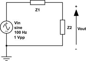
| Z1 | Z2 | Measure With |
|---|---|---|
| wire | open | Multimeter |
| wire | open | 1x Scope Probe |
| wire | open | 10x Scope Probe |
| wire | open | Teensy |
| 10 \(\Omega\) | 20 \(\Omega\) | Multimeter |
| 10 \(\Omega\) | 20 \(\Omega\) | Teensy |
| 1 k\(\Omega\) | 2 k\(\Omega\) | Multimeter |
| 1 k\(\Omega\) | 2 k\(\Omega\) | Teensy |
| 100 k\(\Omega\) | 200 k\(\Omega\) | Multimeter |
| 100 k\(\Omega\) | 200 k\(\Omega\) | 1x Scope Probe |
| 100 k\(\Omega\) | 200 k\(\Omega\) | Teensy |
| 10 M\(\Omega\) | 20 M\(\Omega\) | Multimeter |
| 10 M\(\Omega\) | 20 M\(\Omega\) | 1x Scope Probe |
| 10 M\(\Omega\) | 20 M\(\Omega\) | 10x Scope Probe |
| 10 M\(\Omega\) | 20 M\(\Omega\) | Teensy |
You will be asked to measure the output Voltage with the devices in the “Measure With” column, but some of the devices in the “Measure With” column may be unfamiliar to you. The devices are described below, and datasheet links are provided for each of them. To finish this section, you will need to read these datasheets to find the input impedance and the measurement uncertainty of each device.
- “Multimeter” refers to the multimeter chained to your desk. Our multimeters are the Greenlee DM-210A Digital Multimeter. Since the \(V_{out}\) node will very with time, you should be sure to measure it with your multimeter set to AC mode. The uncertainty listings for multimeters can use unusual units (e.g.: dgt and rdg), so don’t forget about this document on multimeter specifications that we also link on the lectures page.
- “1x scope probe” refers to using a BNC cable with hooks directly connected to an oscilloscope input. BNC cables don’t have datasheets worth reading for this lab because they’re just wires, so they have a low series impedance. However, the oscilloscope itself (an Agilent 2024A, which has this datasheet) has an input impedance and accuracy that you will need to look up. You can also create a 1x probe by using an oscilloscope probe with a switch set to 1x mode, and it will behave the same way as a BNC cable. When you are using a 1x probe, you must change the channel setting of the oscilloscope to be 1x. Note that some scopes call the channel setting 1:1 instead of 1x.
- “10x scope probe” refers to connecting a standard oscilloscope probe (set to 10x mode if there’s a switch) to an oscilloscope input. The gray scope probes in the lab are Keysight N2842A probes, and the black scope probes in 10x mode have a similar input impedance. Note that the input impedance of a scope probe is added in series with that of the oscilloscope itself, so the datasheet may report a total “terminated impedance” that includes the input impedance of the oscilloscope. When you are using a 10x probe, you must change the channel setting of the oscilloscope to be 10x. Note that some scopes call the channel setting 10:1 instead of 10x.
- “Teensy” refers to making an analog measurement with your Teensy. You made similar to the measurements in Section 2. You made some calculations of the uncertainty of the Teensy, which arises from the size of the Teensy unit, in Section 2, and you can find information about Teensy input impedance in the videos.
- Though this is not in the “Measure With” column, you will also need to find the output impedance and amplitude uncertainty of your signal generator. If you are using the scope-integrated WaveGen output, then you can infer the output impedance and find the uncertainty in the oscilloscope manual. If you are, unusually, using a stand-alone function generators (an HP33120A), you can find these values in the datasheet.
Do the following
- For the circuit shown in Figure 1, and for each of the values of Z1 and Z2 and the measuring instruments in Table 1, calculate the expected output voltages with confidence intervals accounting for uncertainty in both components and instruments. Assume the resistors are 5% resistors. Be sure to include the effects of instrument loading in your calculations. Note that these analytical calculations can be made during prelab.
- Build several copies of the circuit in Figure 1, one for each pair of Z1/Z2 values in Table 1. These can all be built simultaneously on the same breadboard if you lay it out carefully. Please trim your resistor leads so that they lie flat on the breadboard.
- Measure and record the value of each component used in your construction, then recalculate the output voltages using your measured component values.
- Drive the circuits using a signal generator and measure the output voltage with each of the instruments in the table.
- Check whether or not the measured voltages lie within the predicted confidence intervals. Recall that you have two sets of predicted voltages, one based on nominal component values and one based on measured component values, so there are two sets of confidence intervals to check against. Also look at the percent error between the predictions and the measurements.
If you are having difficulty with the 10 M\(\Omega\) / 20 M\(\Omega\) experiments, try pulling the resistors out of the breadboard and twisting them together in the air. Leakage currents in the breadboard can cause issues with that measurement.
- When you are using a multimeter, think carefully about whether it should be set to measure an AC voltage or a DC voltage.
- Be sure to set the oscilloscope channel to match your probe. The scope channel should be 1x with a 1x probe and 10x with a 10x probe.
- Function generators have a confusing setting called “OUT TERM”. Be sure it is set to “Hi-Z”, especially if you are seeing a factor-of-2 error in your measurements. (See the videos for an explanation of what this setting does.)
- Make sure all your equipment and circuits under test share the same ground. Be particularly careful with oscilloscope ground clips, which are connected to earth ground, so you can’t hook them up in the middle of a circuit. Measure differences with the scope by using two probes, not by putting the ground clip on a non-ground node.
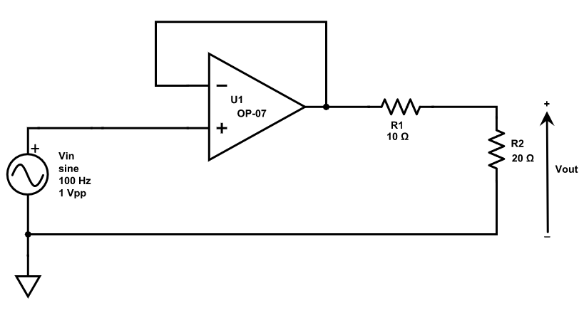
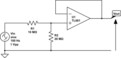
4 Resistor Dividers with Op Amps
Build the circuits in Figure 2 (a) and Figure 2 (b), and measure \(V_{out}\) for both circuits with the multimeter. In both cases, power the op-amp with ±15 V. Compare and contrast your results with equivalent cases (same Z1 & Z2, measured with multimeter) from Section 3. What is the function of the op-amp in each of these measurements?
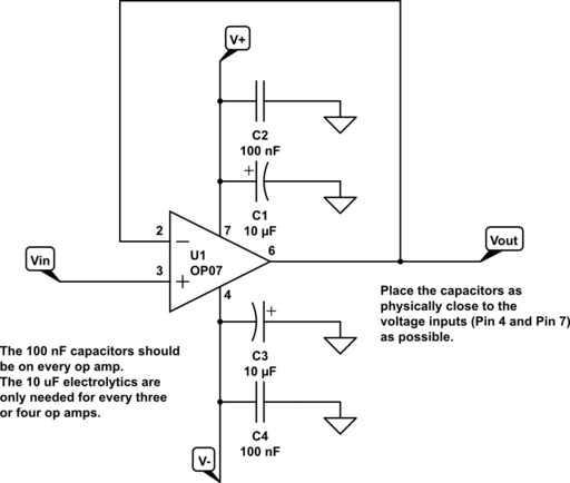
Because this is your first time building op-amps (look forward to many more in lab 3!), we provide this diagram that may help with wiring up your first OP07. Each of the connections on the diagram is labeled with the OP07 pin number. Don’t forget that pin numbers start in the upper left of the chip and wrap around it counter-clockwise. The capacitors, called decoupling capacitors, are important to include even if their purpose may seem unclear. See the callout note below for more details.
- Neatly laid out protoboards work better. Seriously, they do. They’re easier to troubleshoot as well. Please take the time to do it right.
- Keep your leads short and close to the board.
- Strip off the minimum amount of insulation to let your patch wire work; Don’t have big bare areas that can touch other things and short.
- Trim your resistors and capacitors to keep the components close to the boards. Don’t leave the leads long. Get the components down by the board.
- Use the long busses for power only. Do use them for power and ground. Don’t use them for signals. Use bypass capacitors (see below) on your power busses.
- To the extent possible use coaxial cables to get signals on and off of your board. Put the input signals onto the board as close to the circuit inputs as possible. For example, use a coaxial cable with BNC connectors from the signal generator and then put spring-loaded mini-clips on the other end. Connect the mini clips to your circuit input and ground.
- If you are using dual supplies for your op-amps, have three power busses: V+ connected to the +20 V output on your power supply, V– connected to the –20 V output on your power supply, and GND connected to the COM output on the power supply. You can adjust your supply voltage to be anything from ±1 V to ±15 V depending on what chips you are using.
- If you are using a single supply for your op-amps, have two power busses: V+ connected to the +20 V output on your power supply, and GND connected to the COM output on the power supply. You can adjust your supply voltage to be anything from +1 V to +15 V depending on what chips you are using.
- Color code your wiring. A common practice is to use red for V+ power, black for V– power, green for ground, and white or blue for signal lines. If you have a rat’s nest of all red wires, neither the professors nor the proctors (nor you for that matter) will be able to figure out what goes where.
You may have noticed that the circuit has many capacitors connected to its power rails. These are called decoupling or bypass capacitors and they help to stabilize (in a feedback sense) the operational amplifier. The high gain of operational amplifiers can cause op-amps to interact with long power busses to cause oscillations. This manifests as intermittent, large noise in the output of the circuit. You can almost totally eliminate this issue by placing bypass capacitors between the power supply pins and ground as close as physically possible to each op-amp.
Standard practice recommends both a 10 µF electrolytic capacitor and a 0.1 µF standard capacitor. For E80 you can get away with just the 0.1 µF standard capacitor. If you use electrolytic capacitors, remember that they are polar and if you put them in backwards they won’t work and may explode.
For dual supplies the capacitors run between V+ and ground, and V– and ground. For single-sided supplies, they run between V+ and ground. The circuit below shows a unity-gain buffer amp with dual power supplies and bypass capacitors.