E80 Project Build, Test and Integration
After the proposal and jump start, your job is to build your robot. There are three major steps in a robot build: making a breadboard prototype, making a soldered PCB, and mechanically integrating your PCB and sensors into your robot frame. You should aim to check in with a professor after each of these steps.
Breadboard Prototype
The first step in building a robot is building a breadboard prototype of all of your sensors. You should be able to start building this right away because this prototype should match the design from your proposal (though, of course, feel free to update and change things if you realize you made a mistake).
Your goal is to do all of the following:
- demonstrate your sensor circuits working on a breadboard, which you can verify with function generators and oscilloscopes. If necessary, write software to drive sensors (e.g.: time-of-flight sensors need special software). However,
default_robot.inologs analog values, and it should work for most projects without modification.
- stimulate your sensors with appropriate environmental quantities (temperature, salinity, etc.)
- record your environmentally stimulated sensor outputs on your Teensy.
Here are specifications we are checking for in the live demo:
- Power from 12 V from the supply. Current should be reasonably low (a few hundred mA at most)
- Each sensor signal has appropriate stimulus that matches conditions at Dana Point
- Output signal uses most of the range but stays between 0 V and 3.3 V (measured w/ oscilloscope)
- Sensor(s) are in communication with the Teensy on the MTB and signal stays between 0 and 255.
- Everything but voltage regulators fit on one protoboard
- Appropriate software written if necessary
This step usually takes one week of the build. Try to demonstrate a working prototype to a professor at the end of the first build week. Be careful with your construction; building these circuits neatly helps with debugging this week, and with the transfer to your protoboard next week.
Soldered PCB
After you have tested all of your sensors and demonstrated that they work, you need to transfer them to the PCB that will go in your AUV.
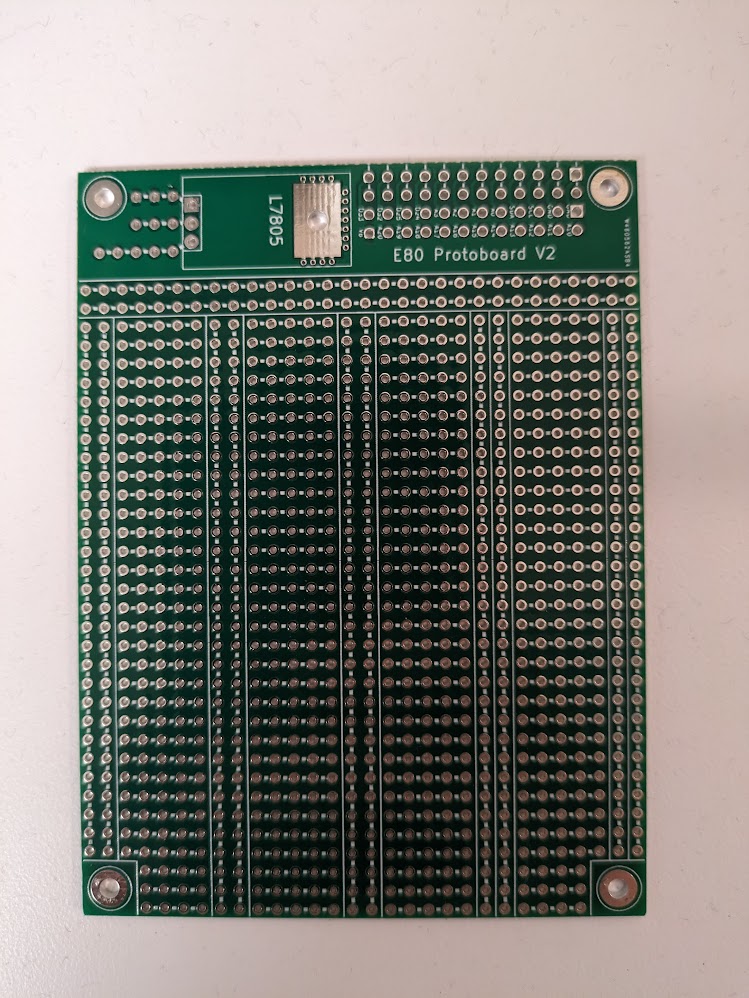
We have designed PCBs called protoboards, pictured in Figure 1, and they are usually the easiest way to mount your components for use in your AUV. Protoboards are laid out like two halves of a breadboard side-by-side, so you can transfer your circuits from the breadboard prototype exactly onto them. They also have an area at the top for a 5 Volt regulator (the L7805 section). They connect to the motherboard as pictured in Figure 2.


Some helpful guidelines:
- Solder parts like the bypass capacitors and assorted resistors directly to the PCB.
- For more complex parts, such as 16-pin DIP op-amps, solder a socket in place and mount the part in the socket so you can replace it if something goes wrong.
- Battery power available to your protoboard, but no regulated voltage supplies are available, so add voltage regulators if needed.
- There are special areas on the protoboard layout for voltage regulators. See the L7805 section of Figure 1
- The screw holes on all of the boards are grounded.
- Good wiring technique and tight layout will make your robot much more reliable and easier to debug.
- You should use stranded wire whenever the wire will be subject to flexure or bending during use, disassembly or reassembly. It is much less likely to break under strain than solid core wire. As a general rule, when connecting two points on the protoboard use solid wire, when connecting to anything off board, use stranded wire.
- If you are going to have connections to a penetrator bolt (more details below), it is helpful to be able to swap the penetrator bolt out if it breaks. Instead of soldering penetrator bolt wires to your Teensy, solder male-female jumper wires to your board so that you can attach the jumpers to the dangling wires from the penetrator bolt. (Though beware of wear cycles on the jumpers, it is possible to get a flaky connection out of them if you plug and unplug many times.)
This should be completed by week two of the build. Show your integrated robot to a professor and perform the same experiments that you used for the breadboard prototype to verify that your soldered board is working. There are three differences from the breadboard demonstration in the previous week:
- You must use a soldered protoboard for the demonstration instead of a breadboard; every circuit should be fully assembled.
- You must power your protoboard from a battery, not the supply,
- You must take your logged data off of your SD card and plot it in Matlab for the professor. You can’t just show oscilloscope and serial outputs.
Be ready to explain how you’re going to make adjustments on the day of deployment if you need to do on-site calibration, which is common for some sensors (e.g.: light intensity varies a lot between lab and the beach).
Mechanical Integration
Finally, you need to assemble your frame, adjust your ballasting, build sensors and sensor harnesses, modify your waterproof box to admit your sensor cabling (and any additional cabling you need), and mount your electronics in your box.
You may need to make penetrator bolts for this project stage. A method for applying marine epoxy to bolts that have been drilled out can be found here. Remember that marine epoxy needs to dry overnight, so making these bolts requires two days because epoxy is applied twice. Be sure epoxy always dries in a fume hood: staff can show you an appropriate hood to use. We use 1/4” holes for our penetrator bolts and we hold the undrilled bolts in vises while drilling out the central hole. We find that six wires is about the maximum that we can fit into one bolt before the epoxy starts failing. You will also need to drill holes for these penetrator bolts in your project box. Be sure to use 1/2” step drill bits (which we have in our cupboards) to drill out the holes. Standard drill bits will result in ragged holes that are not watertight.
As you finish your assembly, here are a set of questions you may want to complete:
- Do you have all your sensors built and attached to appropriate lengths of stranded wire?
- Do you have mount points for your sensors on your frame?
- Do you have penetrator bolts built for all your cabling needs?
- Is your box waterproof with penetrator bolts in place? Conduct this test first by dunking in the E80 lab, then leaving it submerged for 30 minutes in the tank and checking for any moisture in the enclosure. (It can help to dry off the outside before opening it to make sure you’re not brining moisture with you.) DO NOT PUT YOUR MOTHERBOARD IN THE BOX FOR THIS TEST
- Can all your electronics and battery fit into the box?
- Leaving the motherboard disconnected from power and sealing hte battery leads with electrical tape, are you waterproof with electronics in the box?
- Does your frame have appropriate holes so it floods with water?
- Is the combination of your frame and box neutrally buoyant? If not, how much ballast do you need?
- Do your motors have enough drive, and are their drive strengths close to one another?
- Can the sensors, motors and box be mounted securely to your frame? Even if you shake it a bit?
- Can you fully operate your robot in a dry test? With the electronics in the box, powered from the battery, can you get signals from your sensors logged to your SD card?
- What about in the tank?
This work should be done before the first deployment, which takes place roughly a week after your soldered demonstration. The sooner the better, it’s great to demonstrate mechanical integration and a soldered demonstration at the same time.
You don’t need to show your professors anything specific for this checkoff; we’ll see your waterproofing in action in the deployment