Lab 3 Writing Assignment
Electrical Schematics and Mechanical Drawings
Writing Assignment
In this writing assignment you will learn to make high quality electrical schematics and mechanical drawings. You’ll then write text to describe the operation of the electrical system and the key aspects of the mechanical design presented.
Statement of Work
Prepare high-quality electrical schematics and a mechanical drawing to include in a methods section of a technical memo describing the operation of the turbidity meter you built in Lab 3. You should include a schematic for your 555 timer circuit and your transimpedance amplifier. The accompanying text should describe how the circuit and cuvette holder are used to build the turbidity meter.
An electrical schematic describes the functional connection of the components in an electrical circuit. It does not directly represent the physical layout of the circuit in 3d-space on a breadboard or printed circuit board. However, there are certain conventions you should follow when drawing your schematic to allow it to be easily read and understood. These are detailed in the lab submission sheet and the specs below.
For this assignment, draw schematics for the 555 timer circuit and the transimpedance amplifier you developed for your turbidity meter. Ensure your schematics follow all the proper conventions as detailed in the specs below and in the lab manual. After each schematic, include a 100-150 word section of text to describe its design and operation.
The mechanical drawing for this lab is a three-dimensional view of the 3d-printed cuvette holder for the turbidity meter. Your drawing should convey to the reader the key features of the design along with the most important dimensions needed to understand the scale of the design. It does not need to include all the relevant dimensions in order to manufacture the part. The function of the diagram for the written assignment is to communicate how it is used in the experiment. Include a 100-150 word section of text to describe how the cuvette holder is used in the turbidity meter.
Learning Objectives
By the end of this writing assignment you will…
- Draw a neat and complete electrical schematic.
- Create a clear mechanical drawing with relevant details included.
- Write text to reference the schematic and drawing to explain the operation of the turbidity meter.
Required Resources
Specifications
Effort
Completion
Electrical Schematics
Mechanical Drawings
Supporting Text
Tools for Mechanical Drawings
You may use whatever tool you are most comfortable with for preparing your mechanical drawings. SolidWorks is a good choice since you learn it in E4, but sometimes can be difficult to run on your personal computer. Onshape is a popular alternative which runs in your browser and has free education accounts.
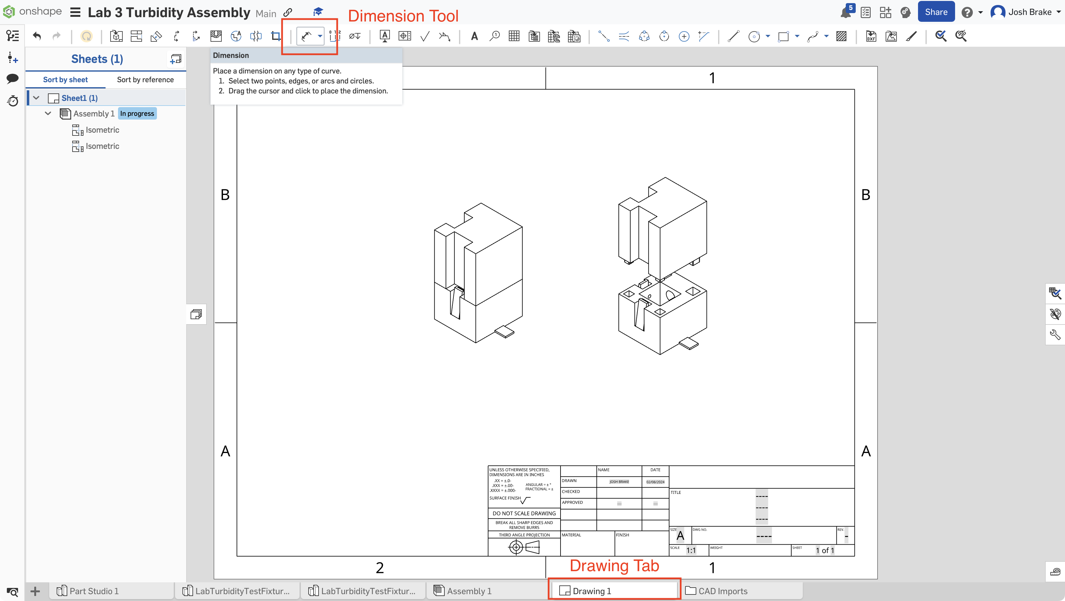
If you’d like to use Onshape, first create an account. Then, you can create a new workspace and import the .sldprt files for the cuvette holder. Alternatively, you may directly make a copy of this Onshape document, which has the parts already imported and a drawing made to which you can directly add relevant dimensions for your figure.
The screenshots below in Figure 1 and Figure 2 show how to copy the workspace and add dimensions.

